
Aluminum to Copper FSW: A Dissimilar Welding Process Guide
Table of Contents
- What Makes Aluminum to Copper FSW Different from Same-Alloy Welding?
- Which Process Parameters Matter Most for Aluminum-Copper Joints?
- Tool Offset Before Rotation Speed
- Why Copper Placement on the Advancing Side Usually Works Better
- What Machine Specifications Do Al-Cu Dissimilar Welds Demand?
- How Do You Keep Tool Wear Under Control in Al-Cu FSW?
- How Do You Qualify Aluminum-Copper FSW and Move Into Production?
- What a First Article Test Should Cover
- What Else Do Engineers Ask About Aluminum-Copper FSW?
- Can Aluminum to Copper FSW Replace Bolted Busbar Joints?
- Why Do Intermetallic Compounds Still Form in a Solid-State Process?
- Do I Need a Different FSW Tool for Every Aluminum-Copper Part?
- How Thin Can Aluminum-Copper FSW Go?
Aluminum to copper FSW works in production, but only when engineering treats it as a machine and tooling problem rather than a parameter recipe. In our process trials, the most damaging failure is not intermetallic formation alone. It is a spindle that runs out of torque on the copper side or a tool that erodes after a few dozen meters. This article walks through the process window, machine envelope, tool material strategy, and qualification steps that separate a repeatable Al-Cu weld from a laboratory curiosity.
What Makes Aluminum to Copper FSW Different from Same-Alloy Welding?
Aluminum and copper do not fuse well. The same qualities that make copper an excellent conductor also make it a difficult welding partner: high thermal conductivity pulls heat away from the joint, while the Al-Cu system forms brittle intermetallic compounds even at temperatures below either metal’s melting point. In same-alloy FSW, the engineer manages one flow stress and one recrystallization behavior. In Al-Cu FSW, the pin is stirring two materials with very different strength and thermal response at the same time.
That asymmetry drives every downstream decision. The copper side resists plasticization more than the aluminum side, so tool offset, spindle torque, and axial force all become variables rather than fixed machine defaults. A weld that looks acceptable on the surface can still contain a thin intermetallic band that fails under bending or thermal cycling. The production question is not whether the weld can be made. It is whether the process can hold the same interface quality for thousands of parts.
Which Process Parameters Matter Most for Aluminum-Copper Joints?
Three parameters decide most Al-Cu joint outcomes before tool design even enters the discussion: tool offset, rotation speed, and travel speed. I rank them in that order because tool offset changes the physical location of the material mixing zone. Rotation speed and travel speed only tune heat input within that geometry.
Tool Offset Before Rotation Speed
Tool offset is the least forgiving parameter in aluminum-to-copper FSW. When the pin center sits exactly on the joint line, it pushes copper fragments into the aluminum matrix and creates a scattered intermetallic distribution that is difficult to control. We shift the tool toward the aluminum side so the pin stirs mostly aluminum and the shoulder only drags a controlled amount of copper into the weld. That small lateral shift, often less than the pin radius, matters more than a 200 rpm speed change.
Why Copper Placement on the Advancing Side Usually Works Better
For most Al-Cu butt and lap configurations, placing copper on the advancing side and aluminum on the retreating side gives cleaner material flow and better consolidation at the interface. The advancing side experiences higher shear strain, which helps the harder copper participate without forming lumped copper islands. There are exceptions for very thin copper or special joint stacks, which is why we do not treat this as a universal rule.
What Machine Specifications Do Al-Cu Dissimilar Welds Demand?
Copper changes the machine requirement curve. A spindle sized for aluminum tube or plate can lose speed or stall when the pin enters a thick copper section. The machine does not need to be exotic, but it does need the right torque, force, and control combination for the copper share of the stack.
| Design Factor | Aluminum-Only Baseline | Aluminum-Copper Shift |
|---|---|---|
| Spindle torque | A 112 Nm spindle covers many thin 6xxx applications | Copper sections above roughly 3 mm often move the requirement to 200 Nm or higher |
| Z-axis force | 30 kN is common for sheet and plate work | Thicker busbars and large contact pads can require 60 kN to 200 kN |
| Machine frame | C-type machines handle compact parts | Gantry or heavy-load machines fit long busbars and large panels with copper sections |
| Process control | Position control may work for simple coupons | Force control with torque and temperature logging becomes the practical default |
| Cooling and runout | Standard spindle cooling is adequate | Copper heat conduction demands stable spindle temperature and low holder runout |
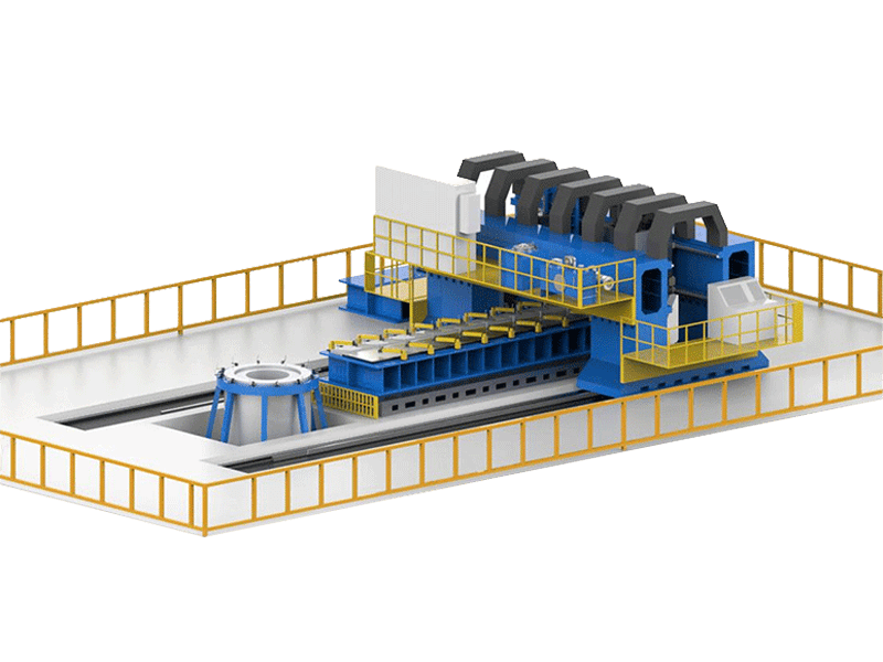
AEE spindle series runs from 112 Nm to 874 Nm, so the same machine platform family can cover thin battery cell tab welding and heavy copper busbar applications. The heavy-load option also delivers 200 kN Z-axis force for single-side welds up to 100 mm in aluminum and 35 mm in copper.
If your Al-Cu program includes copper thickness beyond 10 mm or a long busbar with high current density, confirm the spindle torque and force control envelope before finalizing a machine specification. Send your copper grade, part thickness, and weld length to [email protected] and we will check the required machine and fixture configuration against your production target.
How Do You Keep Tool Wear Under Control in Al-Cu FSW?
Tool wear is where Al-Cu FSW gets expensive if the wrong tool grade is selected. Copper’s higher flow stress and the elevated interface temperature accelerate erosion on steel tools. We start with tungsten-based tools for production because they hold pin geometry far longer than heat-treated tool steel. The exact grade and coating depend on copper temper, aluminum alloy, and annual volume. A tool that survives a 300 mm coupon may still fail before one shift on a full production run.
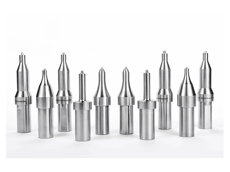
Tool design also changes. A threaded conical pin with a slightly concave shoulder works well for many Al-Cu lap joints because it consolidates material without excessive vertical mixing. For sealed enclosures or circular joints where an exit hole is not acceptable, retractable pin tooling removes the keyhole before the tool retracts. The tool is not a general-purpose consumable when copper is involved. It is part of the process qualification.
Al-Cu tooling life often depends as much on holder runout and spindle rigidity as on tool grade. <AEE provides customer with optional features FSW tool> covers optional FSW tool features such as coolant-through tooling and controlled retraction that change behavior in mixed-material joints.
How Do You Qualify Aluminum-Copper FSW and Move Into Production?
Qualification for Al-Cu components has two tracks: mechanical joint quality and electrical or thermal function. A microsection on its own is not enough. For busbars, we cross-section to check interface mixing and void distribution, then measure joint resistance and temperature rise under load. For cooling plates and sealed enclosures, leak testing matters as much as tensile strength. The first article should be tested in the condition closest to field service, not only as an as-welded coupon.
What a First Article Test Should Cover
At minimum, a production-feasibility Al-Cu first article should include:
- Macrograph for tunnel, void, copper island, and interface continuity
- Tensile or shear test depending on joint configuration
- Electrical resistance measurement for conductor applications
- Thermal cycling or load test for parts that see current or thermal stress
- Leak test when the weld forms part of a sealed enclosure
The first article should run on the same machine class and fixture concept planned for production. A coupon welded on a small C-type machine does not validate a long busbar that will run on a gantry machine. We run feasibility welds on the actual production machine family because clamping, tool deflection, and heat extraction all change with machine architecture.
For programs that need a qualified Al-Cu process before machine purchase, <Customized Dissimilar Material Welding Manufacturers in China> covers how FSW manufacturers in China structure feasibility trials, tooling iterations, and process sign-off for mixed-material joints before production equipment is committed.
Once the first article passes microsection, mechanical, and electrical checks, the real risk moves to machine repeatability and tool life across the production run. That is the point where supplier process data is worth more than a generic feasibility promise. Send your aluminum grade, copper grade, part thickness, joining configuration, and monthly volume to [email protected] or call +86 18325808715. We will run a feasibility weld on the appropriate machine class and return a tooling and production plan for your specific Al-Cu joint.
What Else Do Engineers Ask About Aluminum-Copper FSW?
Can Aluminum to Copper FSW Replace Bolted Busbar Joints?
In many high-current busbar and battery tab applications, yes, when the joint is designed as a lap or edge configuration and validated for electrical resistance. A bolted joint has known contact resistance and a service history. An FSW joint replaces that mechanical interface with a continuous metallic path, but it only earns its place if the intermetallic layer stays thin and the joint cross-section remains stable under thermal cycling. We recommend running a thermal cycling test at the expected current profile before switching from bolts to welds.
Why Do Intermetallic Compounds Still Form in a Solid-State Process?
A common assumption is that solid-state welding prevents intermetallic formation. It does not. Aluminum and copper can form CuAl2 and other intermetallic phases at temperatures well below melting, especially under the strain and exposure time in a stirred weld zone. FSW controls the reaction by reducing peak temperature and dwell time, but it cannot eliminate contact between the two materials. The engineering target is a thin, continuous intermetallic layer rather than a thick, scattered band.
Do I Need a Different FSW Tool for Every Aluminum-Copper Part?
It depends on copper thickness and joint geometry, not on every product number. Thin tab and small busbar families can often share one tungsten-based pin design across several widths, with slight parameter changes. Thick copper plates, long busbars, or closed-loop joints usually need a custom pin length, shoulder profile, or retractable tool design. The practical test is tool life and interface repeatability, not whether the tool turns. If one tool design cannot hold dimensions across the product family, it is time for a separate tool number.
How Thin Can Aluminum-Copper FSW Go?
In thin Al-Cu development work, the first constraint we encounter is not spindle capability, it is part flatness and clamping consistency. Once the workpiece moves, the shoulder dwell shifts and the joint overheats or misses consolidation. We handle thin conductor joints by using a stationary shoulder or a small pin tool with tight Z-axis force control, and by qualifying the process on the same fixture intended for production. Share your exact layer stack and copper temper with [email protected] and we will confirm whether the process can hold the required tolerance.
If you’re interested, check out these related articles:
AEE provides customer with optional features FSW tool
Customized Dissimilar Material Welding Manufacturers in China
Refill Friction Stir Spot Welding (RFSSW)
AEE attend 13th International Symposium on FSW in Kyoto, Japan on 21 – 23 May 2024